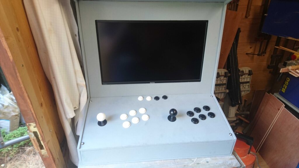
Making a Bartop Arcade Cabinet

Introduction

Making the arcade cabinet was one of the biggest parts of the project. Not only is it a decent size physically, it also is the platform that I’m making the games for, so it needed to be right.

The Design

The design for the cabinet was based on the rough shape of a bar top arcade cabinet. I decided against making a full size one as it would’ve been tricky to move and cost a fair bit more to make. Considering I was doing this project totally out of my own pocket it needed to be as cheap as I could make it while still been good quality.

When it came to getting actual measurements, I used a Legend of Zelda bartop cabinet writeup as a guideline. I mostly used the diagrams to figure out the dimensions I would need for my cabinet. As I was going for a more modern cabinet rather than a retro one, I purchased a budget BenQ 16-9 1080p monitor for the screen. This meant I had to widen the design to suit the monitors dimensions. This actually resulted in a more ergonomic design as the 2 players have a bit more space between their controls.

Materials & Measuring

The material for this project was simple 9 ply, plywood in big sheets. I believe they were 4’ by 8’ but don’t quote me on that. We got 2 sheets cut in half to make squares, due to this we somehow managed to get one for free as the checkout lady, who looked new to the job, but had nice two tone dyed hair got confused and only charged us for the one piece. I’m not complaining as made the materials a tad cheaper.

Measuring each part of the cabinet out was a relatively simple process, having the example project helped getting the right measurements, but measuring it out was tedious as the tools I had to measure with. That being an oversized set square, a bandsaw rail attachment with angles on it and a pencil which was barely visible to me due to my partial colour blindness.

Cutting out the pieces

The next main step was cutting out the pieces. Most of the pieces were simple to cut out as they were 24” wide and varying heights. However not all the pieces were so simple. The sides proved to be difficult as the bandsaw couldn’t get to the line to cut out the shape, the table saw was no better. We ended up getting close with the bandsaw but cutting it out in random shapes in steps and then smoothing it out using a mounted router.

Assembly

Assembling the cabinet together was a puzzle really. It was more or less; get this piece to fit here, at the right angle and with the right depth so it looked good. We put the sides on first so that it could be used as a base for the rest of the pieces and gave the structure some rigidity early on. The bottom piece was a simple fit with a few supports on the interior of the cabinet, though that was the only quote on quote easy piece.

The next piece was the control board, where the joysticks and buttons for both players would be. This was a hard piece as the drill we were using couldn’t handle the cuts for the larger buttons and couldn’t reach over half the buttons on the board. Because of this we ended up using a more powerful hand drill, with one of us drilling while the other held the board as still as possible. This worked surprisingly well all considering. We made two mistakes. The first been the top row of buttons which were there for menus and confirmation in the games. They were supposed to be all in a straight line, but a mistake on measuring meant that the outside hole was slightly higher than intended. We hid that mistake by matching the hole on the other side and making it look natural. However, the left players joystick hole also went a bit weird. While cutting the board wasn’t quite flat on the table and we had a few minor scrapes on the edge which left a not perfect hole. We planned to hide this with the provided covers for the joysticks and left it at that.

After that was probably the next hardest piece which was the monitor. The monitor I had brought for this project was a 21.5” 1080p BenQ monitor. I got this one as the reviews for it on Amazon were good and it had the Vesa 100 x 100, Vesa been a universal wall mounting size format with several variations, most monitors you buy will have them. I planned to use these mounting holes instead of the base that came with the monitor when mounting it into the cabinet as it would be easier to maintain. The piece itself first needed cutting. It was the standard 24” wide but needed a hole in the piece for the monitor screen to show through. I went with the monitor been behind the board, so it added a little depth to piece which was needed. The biggest challenge here was getting the mounting right, which ended up requiring a lot of little pieces to get the mounting screws far enough away to not cause damage to the monitor while also holding it firmly in place. As with the majority of the screws in this project we used a wood glue along with screws to hold everything in place. The exception here is that the monitor could be removed from the piece if needed by unscrewing the 2 screws either side holding it in place. This may prove to be useful later on if I decided to repaint the cabinet.

Next was the speakers. To save on cost and as I happened to already have some, I reused an old Design Tech project that I did in Year 11. This been a RKAmp4 kit which we assembled as part of a speaker project. Now I kept mine and the sound quality is actually not too bad for a simple kit. It does have a downside that is phone signal interference is picked up, but this is something I may be able to fix in the future. The board itself and the speakers all still worked, it did need a heatsink to stay cool, which was mentioned in the documentation for the product when used with high power (12V). Conveniently the amplifier which was the component that needed cooling had a small hole big enough for a screw to go through. So, we attached a left over heatsink which we had found some time ago and mounted it in the optimal position for cooling, drill a hole for a screw and attaching it with a screw through the hole in the amplifier and the heatsink. The speakers were mounted in 2 holes which were cut out with the drill, which took a while as the drill had trouble with the layers in the wood. We managed to get around this by cutting until the drill bit broke through, then flipped the board over and cut in from the other side and meeting in the middle. The speakers also got a little screen which was bit a meshed metal which is just there to protect the speaker from being poked. All the parts were just screwed with standoffs on the PCB board directly to the wood, with some cable management and clips to make the connections to the board less likely to fall out.

The last main panel which is the top front piece is currently not done as I didn’t have the bits for it. This is a part that will be added in part 2. The remaining pieces, those being the back and top pieces were just a simple fit into place with screws so they could be removed as needed. The top had its edges cut at angles so they would end up flush to the front and back pieces.

Painting & Decals

After the main assembly was done it was time to paint. I went with a grey colour for a start, with 2 coats on pretty much every piece, I could always get a new colour and change it later on if needed. I do plan to add some artwork to the sides and control board in the future. This been either acrylic prints or something similar that I can just glue to the pieces with minimal tools to hand.

Conclusion

For a 6-day project, this went rather well. Now its not fully complete, hence this been listed as part 1, but the majority of the work is done. Currently the list of things still to do is:

  • Paint one of the joysticks hole covers white, so it matches the joystick.
  • Attach the joystick covers to control board.
  • Design & print the artwork for the cabinet, though this will probably be done during the unit.
  • Find & attach an opaque material for the top front piece as well as some LED scripts to light it.
  • Drill some holes for air flow
  • Decide on the system to run the cabinet, this being either my laptop or a raspberry pie or something similar.
  • Install internal plugs on an extension bar so the cabinet can be turned on and off when powered at the wall or with a button or switch on the back of the cabinet.